Printed circuit boards (PCBs) are essential components of most electronic devices. They provide the mechanical structure to mount and interconnect electronic components using conductive tracks and pads. There are four main types of PCBs:
Single-Sided PCBs
Single-sided PCBs contain copper tracks on only one side of the board. Components are mounted on the same side as the copper tracks.
Advantages
- Simple and inexpensive to manufacture
- Do not require plated through holes
Disadvantages
- Limited space for components and tracks
- No traces on backside for heat dissipation or shielding
Applications
Simple electronic products like calculators, remote controls etc.
Double-Sided PCBs
Double-sided PCBs have copper tracks on both sides of the board. Components can be mounted on both sides. The tracks on both layers are connected using plated through holes.
Advantages
- More space for components and tracks
- Tracks on backside allow heat dissipation and shielding
Disadvantages
- More complex and expensive to manufacture
- Requires plated through holes
Applications
Consumer electronics, automotive electronics, industrial controls
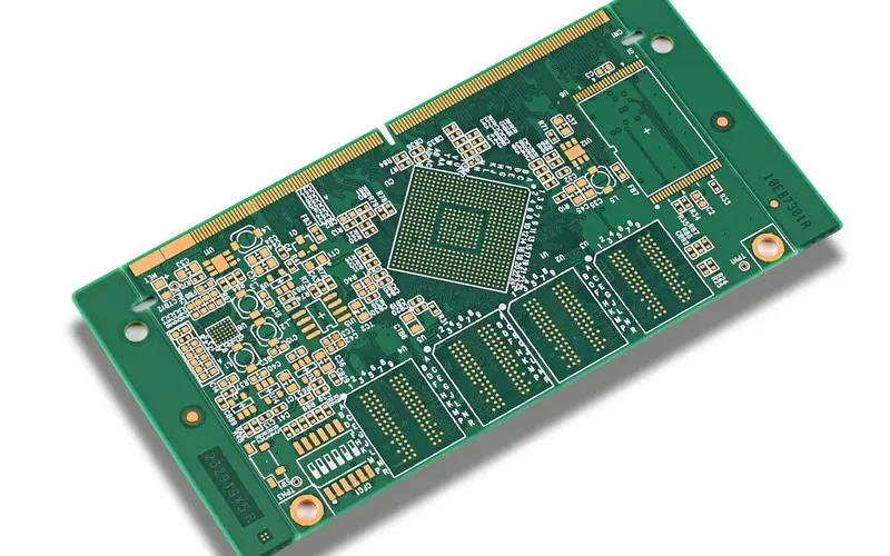
Multi-layer PCBs
Multi-layer PCBs contain more than two copper layers. There are typically between 4 and 16 layers. Each inner layer is separated by a dielectric material. Vias connect tracks between layers.
Advantages
- Very high component density
- Allows complex routing of tracks
- Excellent for high-speed signals
Disadvantages
- Very expensive to manufacture
- Requires advanced PCB fabrication process
Applications
High-speed digital circuits, computing, aerospace and defense
Rigid-Flex PCBs
Rigid-flex PCBs consist of rigid sections interconnected by flexible sections. This allows the PCB to conform to different shapes. The rigid sections provide mechanical support while the flex sections allow dynamic flexing.
Advantages
- Can fit into irregular shapes
- Flexible sections absorb stresses
- Maintains connections despite movement
Disadvantages
- Relatively expensive
- Complex to manufacture
- Flexible sections are less durable
Applications
Consumer electronics, wearables, medical devices
Comparative Table of PCB Types
| PCB Type | Layers | Complexity | Cost | Advantages | Disadvantages |
|---|---|---|---|---|---|
| Single-sided | 1 | Low | Low | Simple, inexpensive | Limited space, no backside tracks |
| Double-sided | 2 | Medium | Medium | More space, backside tracks | More complex manufacturing |
| Multi-layer | 4-16 | High | High | High component density, excellent routing | Very expensive, complex fabrication |
| Rigid-flex | 2+ | Medium | Medium-High | Dynamic flexing, fit irregular shapes | Relatively expensive, complex |
Frequently Asked Questions
What are the different types of materials used for PCBs?
The most common materials used for PCBs are:
- FR-4: Glass-reinforced epoxy laminate. Most common rigid PCB material.
- CEM-1: Cotton paper and epoxy. Used for low-cost PCBs.
- Polyimide: Used for flex PCBs as it has high flexibility.
- PTFE: Polytetrafluoroethylene used for high-frequency PCBs.
- Aluminum: Used when high thermal conductivity is needed.
How are PCBs manufactured?
There are several key steps in manufacturing PCBs:
- Design – The PCB layout is designed using EDA software.
- Prototyping – Prototype PCBs are produced for testing.
- Fabrication – Raw PCB panels are fabricated. This involves processes like laminating, drilling, etching etc.
- Assembly – Electronic components are soldered onto the PCB.
- Testing – Quality testing is conducted to ensure proper functioning.
What are the different methods used to manufacture PCBs?
Some key PCB fabrication techniques are:
- Subtractive process: Copper laminate is etched away to leave required tracks.
- Additive process: Copper tracks are electroplated onto substrate.
- Semi-additive process: Combines subtractive and additive methods.
- Buried and blind vias: To connect inner layers in multilayer PCBs.
- Flexible circuits: Using polyimide substrates instead of FR4.
How to design a PCB?
The main steps in PCB design are:
- Define circuit schematics with components.
- Create PCB footprints for components.
- Layout components and routing connections on PCB.
- Run design rule checks.
- Generate Gerber files, drill files, BOM.
- Test design by prototyping.
- Iterate to refine design.
PCB design requires expertise with EDA software like Altium, Eagle, OrCAD etc.
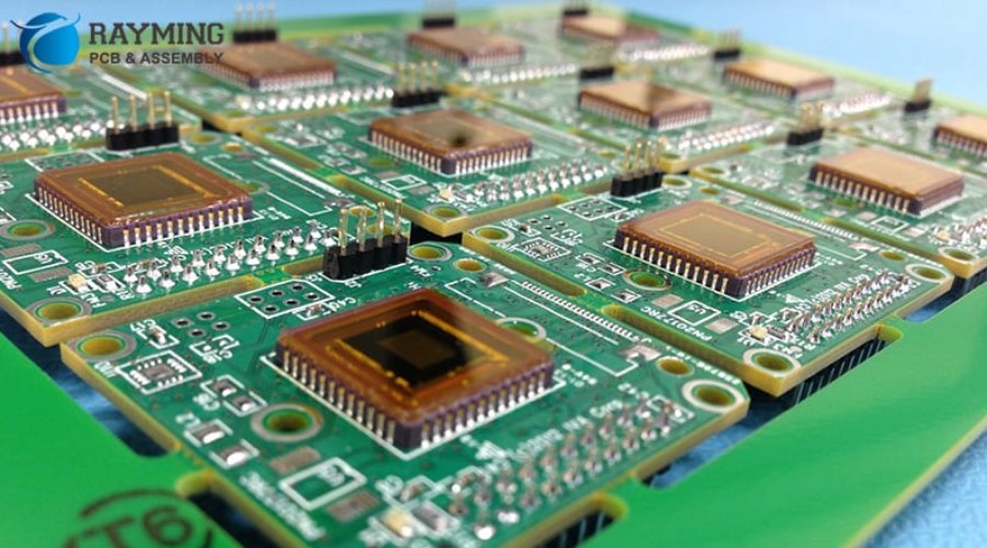
What are some methods used to assemble PCBs?
Some common PCB assembly techniques are:
- Through-hole assembly: Components inserted into holes in PCB.
- Surface-mount technology (SMT): Components soldered directly onto surface pads.
- Reflow soldering: Solder paste melted using infrared heat or hot air.
- Wave soldering: Passing PCB over molten wave of solder.
- Manual soldering: Used for prototypes, repairs and small-scale production.
The assembly method depends on production volumes, component types, quality and cost requirements.


Leave a Reply