
HDI PCB design.
Better decisions.
Design your next HDI PCB with practical stackup guidance, useful engineering tools and a clearer path to fabrication.
Stackups · Microvias · Materials · Signal integrity
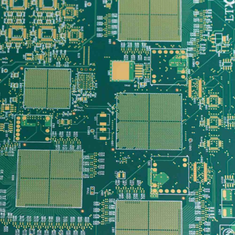 REAL BOARDS. REAL DESIGN DETAILS.
Think it through.
Before you route.
Compare construction choices and prepare your next design review. Change a parameter to explore the tradeoffs.
Via plan: adjacent-layer microvias in the outer 1 layer on each side; review core interconnects separately.
Before release: confirm plane continuity, dielectric thickness, copper balance and microvia reliability with the fabricator. Layer bars are conceptual and not to scale.
Start with the right foundation.
6-layer HDI PCB
Compact control & sensor designs
8-layer HDI PCB
A balanced starting point
12-layer HDI PCB
Room for dense interfaces
14-layer HDI PCB
Plan deeper package escape
Candidate constructions, not fixed recipes. Confirm the actual via spans, dielectric system and process with your fabricator.
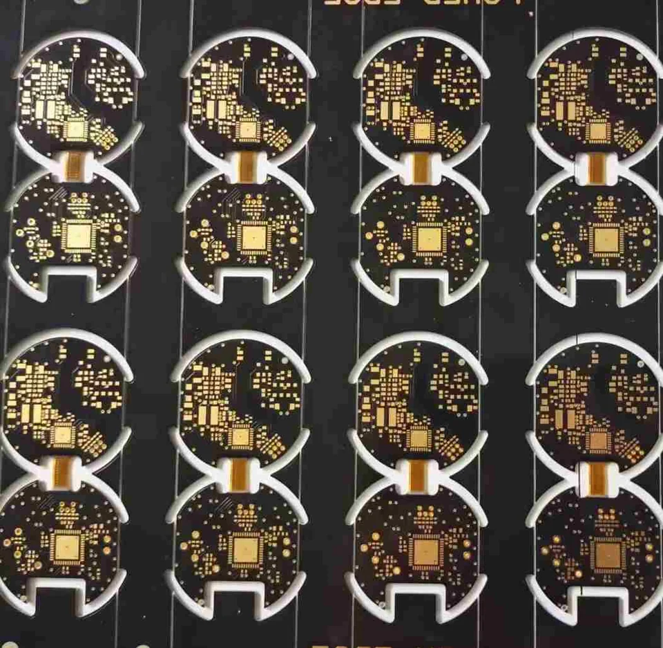
Small features.
Whole-board thinking.
An HDI PCB uses fine conductors, compact via structures and build-up layers to route dense components. The value comes from making the entire construction work together.
Prove the escape first
Use the actual package pin map and manufacturing clearances. Pitch alone does not choose the stackup.
Protect the return path
Give critical routes a continuous reference, including the transitions through a dense via field.
Specify what gets built
Connect via geometry, material, thermal exposure and test evidence in one fabrication review.
Go deeper on the decisions that matter.
HDI PCB design guide: from escape to release
A successful HDI layout starts with package escape, layer allocation and factory-approved interconnects. Detailed routing follows those decisions.
Microvias & interconnectsStacked vs staggered microvias
Stacked microvias share a vertical location; staggered microvias offset successive transitions. The decision trades lateral routing area against construction and interface demands.
PCB materialsSelecting laminate for HDI PCB
Choose a complete laminate system that supports the intended loss budget, thermal history and microvia process. A material trade name is only part of the specification.
A few good questions.
Clearer next steps.
Start with the fundamentals, then verify the details of your own construction.
Read the HDI fundamentalsWhat makes a PCB an HDI PCB?
HDI stands for high-density interconnect. Compact interconnects, fine routing and build-up structures help increase wiring density. A high layer count by itself does not establish an HDI construction.
Should I choose 1+N+1 or 2+N+2?
Start with the simplest option that routes the actual package escape and preserves reference planes. A second build-up adds another connection depth and additional manufacturing considerations. Use a routing study rather than pitch alone.
Are stacked microvias always better?
Stacking can save lateral area. Staggering uses space to offset successive transitions. Either option needs a qualified structure and test evidence relevant to the material and thermal exposure.
Can I use the cost estimate as a quotation?
The calculator is an adjustable, uncalibrated planning model. It exposes the assumptions behind its estimate. Actual price and lead time require a factory review of your files, construction, quantity and test requirements.
What should I send for an HDI PCB inquiry?
Include layer count, outline, thickness, proposed via structure, material, impedance targets, quantity and timing. Describe unresolved decisions. The contact form saves your inquiry and provides a route to continue the quotation discussion.
Bring the requirements.
Start the right conversation.
Share your layer count, via structure, material and quantity. Give the fabrication review a clear starting point.