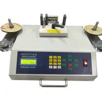
What is SMD?
SMD stands for Surface Mount Device. It refers to electronic components that are designed to be mounted directly onto the surface of a PCB. These components have small metal leads or terminations that are soldered to pads on the PCB’s surface. SMD components are widely used in modern electronics due to their small size, low cost, and ease of assembly.
Advantages of SMD Components
- Smaller size compared to through-hole components
- Higher component density on PCBs
- Faster and more efficient assembly process
- Lower cost due to automated assembly
- Better high-frequency performance
Common SMD Component Packages
- Resistors: 0402, 0603, 0805, 1206
- Capacitors: 0402, 0603, 0805, 1206
- Inductors: 0402, 0603, 0805, 1206
- Integrated Circuits: SOIC, QFP, QFN, BGA
What is SMT?
SMT stands for Surface Mount Technology. It is the process of assembling electronic components onto a PCB using SMD components. SMT involves the use of specialized equipment, such as pick-and-place machines and reflow ovens, to accurately place and solder components onto the PCB’s surface.
SMT Assembly Process
- Solder Paste Application: A stencil is used to apply solder paste onto the PCB’s pads.
- Component Placement: SMD components are placed onto the solder paste using a pick-and-place machine.
- Reflow Soldering: The PCB is heated in a reflow oven, melting the solder paste and creating a strong bond between the components and the PCB.
- Inspection and Testing: The assembLED PCB undergoes visual inspection and electrical testing to ensure proper functionality.
Advantages of SMT Assembly
- High-speed and high-volume production
- Consistent and reliable solder joints
- Reduced assembly costs due to automation
- Ability to handle smaller components and higher component density
What is PTH?
PTH stands for Plated Through Hole. It refers to a type of electronic component that has long metal leads that are inserted into holes drilled through the PCB. These leads are then soldered to pads on the opposite side of the board, creating a strong mechanical and electrical connection.
Advantages of PTH Components
- Strong mechanical connection to the PCB
- Better thermal dissipation compared to SMD components
- Easier to replace or repair individual components
- Suitable for high-power applications
Common PTH Component Packages
- Resistors: Axial, Radial
- Capacitors: Radial, Axial
- Connectors: Pin headers, Sockets
- Transformers and Inductors

SMD vs PTH: Key Differences
| Feature | SMD | PTH |
|---|---|---|
| Size | Smaller, more compact | Larger, bulkier |
| Density | Higher component density | Lower component density |
| Assembly | Faster, automated | Slower, manual |
| Cost | Lower assembly costs | Higher assembly costs |
| Mechanical Strength | Weaker connection to PCB | Stronger connection to PCB |
| Thermal Dissipation | Limited | Better |
| Rework and Repair | More difficult | Easier |
FAQ
-
Q: Can SMD and PTH components be used on the same PCB?
A: Yes, it is possible to use both SMD and PTH components on the same PCB. This is called a mixed-technology PCB. -
Q: What is the difference between reflow and Wave Soldering?
A: Reflow soldering is used for SMD components and involves applying solder paste and heating the entire PCB in an oven. Wave soldering is used for PTH components and involves passing the PCB over a molten solder wave. -
Q: Are SMD components more expensive than PTH components?
A: Generally, SMD components are less expensive than their PTH counterparts due to their smaller size and higher volume production. -
Q: What are the challenges of working with SMD components?
A: The main challenges of working with SMD components include their small size, which can make manual assembly and rework difficult, and the need for specialized equipment for assembly and inspection. -
Q: Can PTH components be used in high-frequency applications?
A: PTH components can be used in high-frequency applications, but their longer leads can introduce parasitic inductance and capacitance, which can negatively impact high-frequency performance. SMD components are generally preferred for high-frequency applications.
Conclusion
Understanding the differences between SMD, SMT, and PTH is essential for anyone involved in PCB Assembly or electronics manufacturing. SMD components and SMT assembly offer numerous advantages, such as smaller size, higher component density, and lower assembly costs. PTH components, on the other hand, provide stronger mechanical connections and better thermal dissipation.
When designing a PCB, it is important to consider the specific requirements of your project, such as size constraints, power handling, and high-frequency performance, to determine the best choice between SMD and PTH components. In some cases, a mixed-technology approach, using both SMD and PTH components, may be the ideal solution.
By familiarizing yourself with these terms and their implications, you can make informed decisions and optimize your PCB designs for manufacturability, reliability, and performance.


Leave a Reply