Introduction
Printed circuit boards (PCBs) are essential components in almost all modern electronic devices. Before mass producing PCBs for a new product, prototypes are often created to test the circuit design and functionality. Building prototype PCBs requires some specialized equipment that allows for small-scale PCB production. This equipment is more affordable and compact than full-scale PCB fabrication machinery.
In this guide, we will look at the key pieces of equipment needed to manufacture prototype PCBs on your own. We will also discuss the prototyping process and provide tips for first-time PCB builders. Learning how to produce prototype boards in-house allows inventors and engineers to quickly iterate on their designs before finalizing circuits for mass production.
Overview of Prototype PCB Manufacturing Process
Here are the typical steps involved in building prototype PCBs:
- Design the circuit board layout using PCB design software.
- Print the layout onto a copper-clad laminate board using a photoresist transfer process. This transfers the circuit pattern onto the copper layer.
- Etch away unwanted copper, leaving only the desired copper traces on the board.
- Drill holes for component leads using a small drill press.
- Populate the PCB with electronic components by soldering them into place.
- Inspect the finished board and test its functionality.
- Repeat and refine the design as needed.
This basic process allows even hobbyists and students to produce their own PCBs at home or in a makerspace. Let’s look at the key pieces of equipment involved.
Essential Equipment for PCB Prototyping
PCB Design Software
To begin, you’ll need software to design the circuit board layout. There are many options available, including:
- Eagle: Very popular freeware tool for hobbyists and makers. Part of the Autodesk family of products.
- KiCad: Another open-source PCB design suite. Has a bit of a learning curve but very powerful.
- Altium: Industry-standard PCB design software. The full suite is expensive but beginner licenses are more affordable.
The software will allow you to place circuit components and route the copper traces that connect them. Most will also let you design schematics and simulate circuits before layout.
Laser/Inkjet Printer
To transfer the PCB layout onto the copper board, you’ll need a printer. Laser printers work best for their high resolution and durability. Inkjet printers can also work well for lower resolution boards. Special toner cartridges are used that resist the etching chemicals.
Laminator
A laminator applies heat and pressure to transfer the toner onto the copper board. A small pouch or roll laminator is sufficient for prototyping needs. The laminated toner mask will protect areas of copper that should remain on the finished PCB.
Etchant Chemicals and Tanks
Etchant chemicals will “eat away” unwanted copper leaving only the desired traces protected by toner. Common options are ferric chloride and ammonium persulfate. You’ll need an etching tank or tray to submerge boards in the liquid etchant. Plastic or glass tanks equipped with a heating element and thermometer work best. Always use etchant chemicals safely by wearing gloves and goggles. Work in a ventilated area.
Drill Press
A small benchtop drill press is required to drill precision holes in the PCBs for mounting components. Look for one with a minimum of 12 speeds and able to use very small drill bits down to 0.8mm. A press with X-Y table allows moving the board for placing holes accurately.
Soldering Tools
You’ll need soldering equipment to attach circuit components onto the PCB. A soldering iron, solder, flux, magnifying glass, tweezers, and fume extractor are essential. A quality fine-tip iron between 15-40 Watts is recommended.
Safety Equipment
Work safely by wearing gloves and goggles when handling chemicals. Use a mask or fume extractor when soldering. Having a fire extinguisher and first aid kit on hand is also a good idea when DIYing with chemicals and electronics.
Prototype PCB Manufacturing Process Step-by-Step
Now let’s walk through the PCB prototyping process from start to finish using the equipment described above:
Step 1: Design the Circuit Board Layout
Use PCB design software to layout your circuit. This involves:
- Placing footprints for components
- Routing connections between pads/pins
- Adding any required text or outlines
- Setting ground planes or polygon fills if needed
Double check the layout for errors before moving forward. The software will also estimate the board dimensions.
Step 2: Print the Layout onto Copper Board
Select a copper-clad laminate board of the required size. Common options are single-sided or double-sided boards. Apply the special toner transfer toner to a laser printer or inkjet if using transparencies.
Print the layout onto the copper board. Place the board in a laminator pouch and run it through the laminator. The heat and pressure will transfer the toner mask firmly onto the copper surface.
Step 3: Etch the Board
Mix and heat the etchant chemicals in a tank or tray. Fully submerge the PCB and agitate lightly until all exposed copper is dissolved. The etchant will not affect toner protected copper traces.
Rinse thoroughly with water and inspect that all unwanted copper has cleared while traces remain intact. Repeat etching if needed. Dispose of used etchant properly.
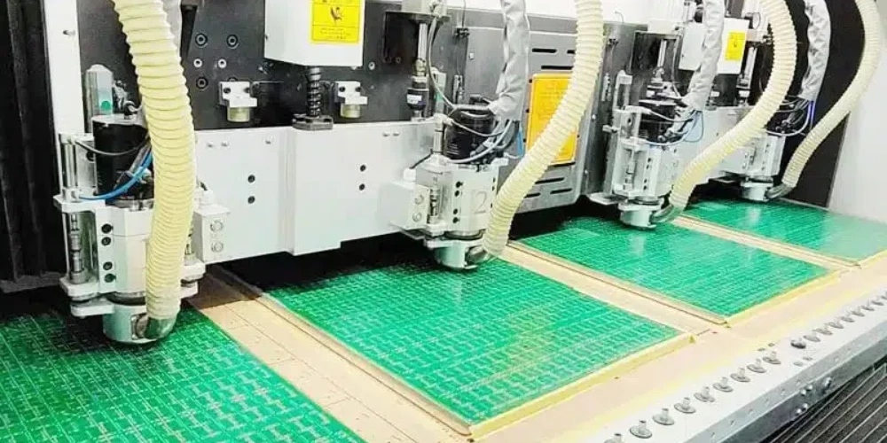
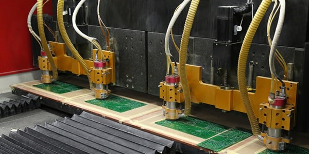
Step 4: Drill Holes
Carefully mark hole locations on the board as designed in the layout. Mount the PCB to the drill press bed. Start with a larger bit to drill alignment holes, then switch to smaller bits for component holes. Drill all holes required.
Deburr the board when finished drilling to remove rough edges from holes. Wipe away drill dust.
Step 5: Populate and Solder Components
Place electronic components such as ICs, resistors, capacitors, etc. onto their matching pads and holes. Solder pins into place being careful not to create shorts. Clip any long leads. Inspect all joints under a magnifier. Reheat and resolder any poor connections.
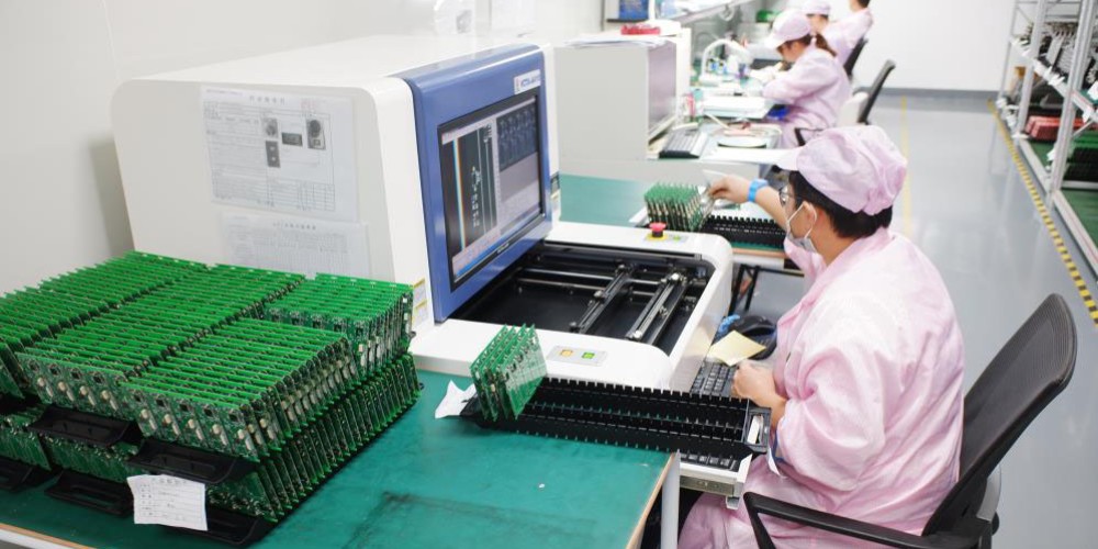
Step 6: Test and Iterate
Inspect for any shorts, opens or errors on the finished prototype PCB. Test its functionality if possible by powering up and evaluating performance. Make notes of any needed improvements in the design.
Repeat the prototyping process using this feedback to further refine the design. Build multiple revisions until the circuit operates as intended before moving to mass production.
Tips for First-Time Prototype PCB Builders
Here are some tips if you’re just getting started with DIYing your own prototype printed circuit boards:
- Start with a simple single-sided board design before attempting more complex multilayer boards.
- Have the board house fabricate the first prototype so you have a reference to compare your own boards against.
- Use soldermask and silkscreen if possible for a professional appearance.
- Use the right amount of solder. Too little or too much can cause issues.
- Find a local makerspace or electronics shop to access specialized equipment.
- Ask electronics technician friends for assistance if you get stuck.
- Be very meticulous and double check every step – precision is critical, especially for drilling.
- Review online tutorials for each piece of equipment and process step before starting.
- Respect all safety precautions when using chemicals or soldering.
With practice, patience, and by learning from failures, you’ll get the hang of producing your own prototype PCBs. The ability to quickly test circuit revisions is invaluable.
Frequently Asked Questions (FQA)
What materials do I need to make PCBs at home?
You’ll need copper-clad laminate boards, transfer toner, etchant chemicals, a drill press, soldering equipment, and safety gear at minimum. PCB design software and a laminator also make home prototyping much easier.
Can I build multi-layer PCBs?
Yes, but they are much more complex to produce yourself. You’ll need to laminate boards together under intense heat and pressure. Single or double-sided boards are recommended for starting out.
How precise does hole drilling need to be?
Very precise – even small deviations can prevent components from fitting or forming good solder joints. Take your time, mark locations clearly, and drill meticulously. Expect to scrap a few boards learning how.
What resolution can I expect from homemade PCBs?
1mm traces and holes are achievable with care using a laser printer and high quality laminator. For finer features, inkjet printers with photoresist can produce traces down to 0.15mm or less.
Can I scale up to produce hundreds of boards?
The home etching process can be slow and laborious. For more than 10-25 boards, consider outsourcing to a professional PCB manufacturer. But DIY is great for small-scale rapid prototyping.


Leave a Reply