Introduction to PCB Assembly
Printed circuit boards (PCBs) form the backbone of most modern electronic devices. PCB assembly involves soldering various electronic components like resistors, capacitors, integrated circuits (ICs), transistors etc. onto a PCB to create a functional electronic circuit. Proper component placement and soldering is crucial for the circuit to function correctly. This article provides a comprehensive guide on PCB assembly, covering topics like:
- PCB manufacturing process
- Common PCB components
- SMT and through-hole components
- Soldering methods
- Cleaning and inspection
- Troubleshooting faulty PCBs
Understanding these concepts will help you assemble robust PCBs for your electronic projects or products.
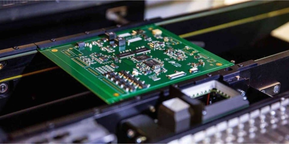
PCB Manufacturing Process
Before assembly, the PCB itself needs to be fabricated. The manufacturing process consists of:
1. Design
The circuit layout is designed in EDA (electronic design automation) software like Altium, Eagle, or KiCad. Footprints for components are added and the PCB is routed.
2. Production
The PCB fabrication starts with a bare FR-4 fiberglass substrate. copper layers are laminated onto the substrate. Photoresist coating is applied and the layers are exposed to UV light through a mask. The unexposed photoresist is washed away, leaving behind the desired copper traces.
3. Solder mask application
A solder mask is applied to protect copper traces from oxidation and prevent solder bridging. Openings are made at soldering pads.
4. Silkscreen printing
Component outlines, labels, and other markings are printed on the solder mask layer to help identify components.
5. Surface finish
A chemical finish like HASL (hot air solder leveling) is applied to facilitate soldering.
6. Testing
The finished PCBs are electrically tested before shipment.
This multi-step process transforms the initial PCB design into a physical board ready for population with components.
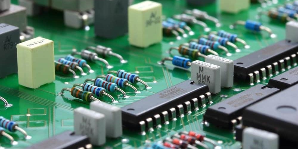
Common PCB Components
Various electronic components need to be soldered onto the PCB to build the target circuitry. Some common components are:
- Resistors – Used to limit current flow in a circuit. Different values are identified by color codes.
- Capacitors – Store electric charge. Include ceramic, electrolytic, and tantalum types. Help filter signals.
- Diodes – Allow current flow in only one direction. Types are signal diode, Zener, LED, and Schottky.
- Transistors – Amplify current or work as an electrical switch. Small signal and power transistors.
- Integrated Circuits – Contain complete electronic circuits with hundreds of components in a single package. Can be analog or digital ICs.
- Connectors – Allow external connections. Common types are pin headers, edge connectors, and USB ports.
- Switches/Relays – Used to open or close circuits electro-mechanically. Help control signals.
- LEDs – Light emitting diodes that produce light when current flows through. Indicates status.
- Buttons/Switches – Manually operated switches to control power or signals.
- Fuses – Sacrificial components that blow to protect against excessive current.
- Inductors – Coiled wires that induce magnetic fields. Filter signals at high frequencies.
- Crystal Oscillators – Generate clock signals with precise frequency for microcontrollers.
Proper identification and handling of such components is vital for assembling the PCB correctly.
SMT and Through-Hole Components
Electronic components come in two main packages – surface mount (SMT) and through-hole:<div class=”table-container”>
| Surface Mount (SMT) | Through-Hole |
|---|---|
| Small rectangular or square packages | Have wire leads to pass through holes |
| Sits directly on top of PCB surface | Must be inserted into plated through-holes |
| Low profile – No wires sticking out | Higher profile with wires protruding |
| Harder to solder manually | Easier to solder by hand |
| Takes less space – good for miniaturization | Requires more PCB space |
| Used for automated PCB assembly | Suited for manual assembly or prototyping |
</div>
A PCB can contain both SMT and through-hole components. Tiny SMT components help achieve compact form factors while through-hole is preferred for connectors or heat-sensitive parts.
Soldering Methods
The two main techniques used for soldering PCBs are:
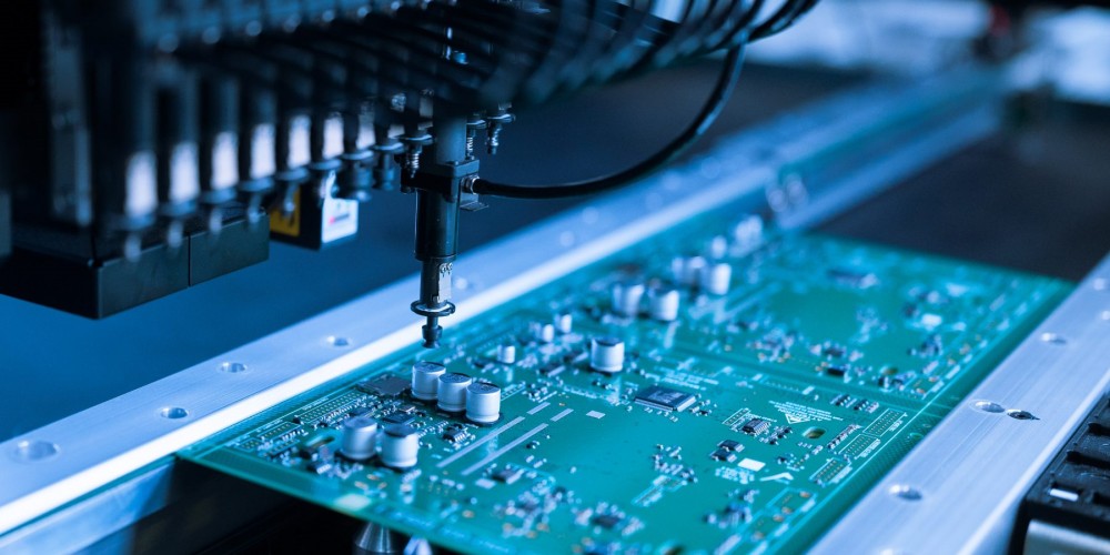
Reflow Soldering
Used to solder surface mount (SMT) components. The steps are:
- SMT components are accurately placed onto PCB pads using pick-and-place machines
- The populated PCB passes through a reflow oven
- The entire board is gradually heated above solder’s melting point
- Solder paste melts, creating reliable joints as it cools
- Multiple small components can be soldered simultaneously
- Well suited for mass production assemblies
Hand Soldering
Manual soldering using a soldering iron. Typically used for:
- Through-hole component termination
- Larger components unsuitable for reflow process
- Re-working faulty solder joints
- Prototyping or small-scale production
Requires skilled operators. Component leads are inserted into holes and soldered individually. Allows inspection and rework of each joint.
Wave Soldering
The assembled PCB passes over a wave of molten solder to simultaneously solder components. Fast and efficient but prone to defects.
Choosing the right soldering method is important based on the components used, scale of production, available tools and operator skill.
Cleaning and Inspection
After soldering, PCBs must be cleaned and inspected:
Cleaning
- Removes flux residues left over from soldering
- Prevent corrosion from leftover flux activators
- Isopropyl alcohol is commonly used
- Specialized PCB cleaning equipment also available
Inspection
- Verifies all components are properly soldered
- Checks for defects like shorts, open joints, bridges etc.
- Visual inspection under microscope
- Automated optical inspection (AOI) systems for high volume
- X-ray inspection reveals hidden flaws
- Flying probe testers perform electrical testing
Thorough cleaning and inspection ensures the soldered PCB assembly meets quality standards.
Troubleshooting Faulty PCBs
Some common PCB assembly problems and their troubleshooting are:<div class=”table-container”>
| Issue | Possible Cause | Troubleshooting |
|---|---|---|
| Short circuits | Solder bridges between pads | Visual inspection. Re-flow or manually clear bridge |
| Open circuits | Cold solder joint | Re-heat joint. Replace component if pad lifted |
| Wrong components | Misplaced components | Compare with Bill of Materials (BOM). Replace |
| PCB damage | Cracks, scratches in traces | Repair with wire jumpers or fiberglass coating |
| Erratic behavior | Loose components | Re-solder all joints. Use adhesive if required |
| Overheating | Wrong voltage rating components | Verify specs. Replace with higher voltage rating |
</div>
Careful visual examination under a microscope along with multimeter measurements can diagnose most assembly issues. The board may need to be re-worked by removing and replacing the faulty components.
PCB Assembly FAQ
Q: What are the typical steps in PCB assembly?
A: Major steps are – PCB fabrication, component placement, soldering (reflow/hand), cleaning, inspection & testing.
Q: How are very small 0201 or 01005 components handled?
A: specialized pick-and-place machines accurately place tiny components. Good lighting, magnification and fine tweezers help in manual assembly.
Q: What is the difference between leaded and lead-free solder?
A: Leaded solder contains lead while lead-free is made from metals like tin, copper and silver. Lead-free is preferred now for health and environmental reasons.
Q: How can PCB assembly quality be improved?
A: By following IPC standards, using certified components, having well-designed solder stencils, matching land pattern sizes to leads, having well-trained operators and using inspection tools like x-ray and AOI.
Q: What are rework stations used for?
A: Rework stations with hot air or infrared heating tools are used to safely remove and replace components on already-assembled PCBs to fix errors.
Conclusion
PCB population with the correct components using appropriate soldering and inspection steps is critical to producing working electronic circuits and products. Engineers and technicians involved in PCB assembly should have sound knowledge of the topics covered in this guide. With attention to detail and quality, robust and reliable PCB assemblies can be manufactured.


Leave a Reply