Introduction to Multilayer PCBs
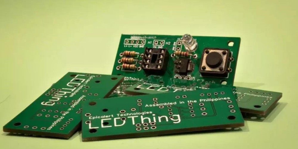
A printed circuit board (PCB) mechanically supports and electrically connects electronic components using conductive tracks, pads and other features etched from copper sheets laminated onto a non-conductive substrate. PCBs can be single sided (one copper layer), double sided (two copper layers) or multilayer (three or more copper layers).
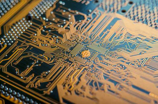
Multilayer PCBs allow more complex circuit designs by allowing traces to cross between layers without intersecting. This is useful for designing more compact and higher density boards with components mounted on both sides. Multilayer boards are used in nearly all modern electronics requiring small, lightweight and efficient circuitry such as mobile devices, computers, automotive electronics etc.
Benefits of Multilayer PCBs
- More routing channels for traces on the internal layers, allowing higher component density.
- Traces can cross between layers, reducing need for jumpers.
- Components can be placed on both sides of the board.
- Shielding can be incorporated by using a whole layer as a ground plane.
- Impedance control is easier compared to double sided boards.
- Better EMI and noise reduction due to ground planes.
- Allows embedding passive components like resistors and capacitors.
Challenges of Multilayer PCBs
- Increased complexity and cost compared to double sided boards.
- Requires advanced CAD tools for multilayer design and layout.
- Layer alignment is critical during manufacturing.
- Testing and debugging is more difficult after assembly.
- Repair and rework is harder once assembled.
- Higher chances of layer misregistration and buried vias.
Multilayer PCB Fabrication
The fabrication process for multilayer PCBs involves first making double sided boards, then laminating multiple double sided boards together under heat and pressure. Here are the typical steps:
1. Making Double Sided Boards
- Coat the raw PCB substrate on both sides with photoresist.
- Expose both sides to UV through the desired circuit pattern film prints.
- Develop the photoresist to remove unexposed areas.
- Etch away the exposed copper to form the traces.
- Strip off the remaining photoresist.
- Drill holes for component leads and vias.
- Metallize the through holes.
This forms a double sided board with the desired trace pattern on both sides and plated through holes connecting the two layers.
2. Layer Stacking
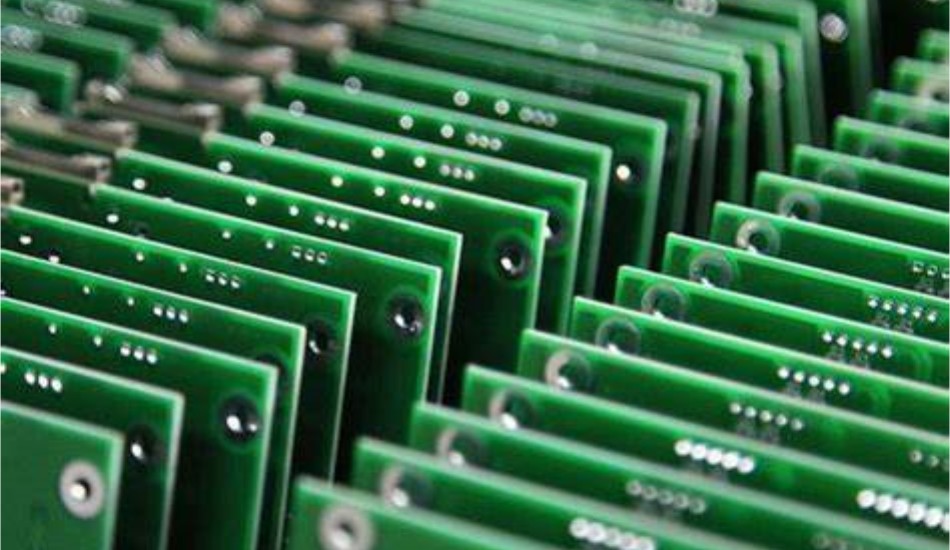
Multiple double sided boards are precisely aligned and laminated together under heat and pressure to form a multilayer board. Alignment accuracy depends on the number of layers.
- Clean the surfaces of the double sided boards.
- Apply bonding agent if using a rigid substrate.
- Precisely align the layers and stack in sequence.
- Laminate the stack under heat and pressure.
The result is a solid multilayer board with copper on the outer layers and in between.
3. Outer Layer Imaging
The outermost layers are now processed similar to a double sided board to achieve the final trace pattern.
- Apply dry film resist on both outer surfaces.
- Expose both sides to UV using the desired circuit image.
- Develop and etch to form the traces.
- Drill holes for vias and components as needed.
- Strip off resist and metalize the holes.
The final multilayer board is now ready for component assembly and testing.
Design Rules and Layout
There are several important considerations when laying out a design for multilayer PCB fabrication:
Layer Stackup
The sequence and thickness of the copper and dielectric core layers must be defined. Common options:
- 4-layer: (copper – dielectric – copper – dielectric – copper)
- 6-layer: (copper – dielectric – copper – dielectric – copper – dielectric – copper)
- 8-layer: (copper – dielectric – copper – dielectric – core – dielectric – copper – dielectric – copper)
The core provides mechanical stability. More layers allow higher complexity.
Trace Routing
- Use the internal layers for power, ground and critical signals.
- Route digital traces on the internal layers when possible.
- Maintain clearance between traces and pads.
- Use vias to transfer traces between layers. Minimize via stubs.
- Match trace impedance to devices when required.
Component Placement
- Place components on both sides for optimal density.
- Ensure components and pads line up across layers.
- Watch component height to prevent shorting between layers.
Board Outline
- Include tooling holes for layer alignment.
- Add fiducials to check alignment during fabrication.
- Define routing channels between board outline and edge traces.
Stackup and Finish
- Define mask and silkscreen layers.
- Specify surface finish e.g. ENIG, immersion silver etc.
- Call out board thickness, copper weights and soldermask details.
Multilayer PCB Assembly
After fabrication, electronic components must be assembled and soldered onto the finished multilayer PCB. Here are some key assembly steps:
1. SMT Component Placement
- Apply solder paste on pads using stencils.
- Place surface mount devices onto paste deposits using pick and place machines.
- Reflow solder to attach SMT components.
2. Through Hole Component Insertion
- Insert pins or leads of through hole components into plated holes.
- Solder pins to pads manually or using wave soldering.
3. Inspection and Testing
- Visually inspect for defects and quality.
- Electrical testing to verify connectivity and function.
- X-ray inspection to check for hidden faults under components.
4. Conformal Coating
- Apply protective coating over the entire assembly.
- Covers components and exposed traces against environmental damage.
- Options include acrylic, urethane, silicone and parylene coatings.
- Mask connectors or testpoints before coating.
5. Backplane and Final Assembly
- For systems with backplanes, install the loaded PCB into the chassis.
- Make electrical and mechanical connection to the backplane.
- Complete hardware assembly and casing.
- Power up and configure the system. Run system level tests.
The assembled PCBs are now ready for functionality testing, packaging and delivery.
Advantages of Outsourcing vs. In-House Production
Many companies face the make vs. buy decision for PCB assembly. Here are some factors when considering outsourcing to a contract manufacturer:
Advantages of Outsourcing
- No need for substantial equipment investments.
- Reduced labor requirements and training costs.
- Expertise in specialized processes like multilayers or high density designs.
- Flexibility in production capacity.
- Faster and predictable turnaround times.
- Additional services like procurement, testing, logistics.
Advantages of In-House Production
- Tighter control over quality and IP protection.
- Better communication and visibility.
- Faster prototyping of new designs.
- Lower costs at very high volumes.
In general, outsourcing is preferred for quick-turn prototypes, low to mid volume production, and for technologically complex designs. High volume commodity products are better kept in-house if capabilities exist.
Key Considerations for Multilayer PCB Assembly
Here are some important factors to review when selecting a contract manufacturer for assembling multilayer PCBs:
- Experience with handling high layer count and fine pitch designs.
- In-house engineering review support for manufacturability.
- Quality certifications such as ISO 9001, IPC, ITAR registration.
- Wide range of assembly capabilities – SMT, thru-hole, BGAs, press-fit etc.
- Flexible and scalable capacity for volumes ranging from prototypes to high volume.
- Communications and program management during new product introduction.
- Quality controls and testing capabilities.
- Supply chain management services for components and materials.
- Geographic location and logistics capabilities aligned with market.
Choosing an established and capable partner reduces risks and ensures high quality results when undertaking multilayer PCB assembly for a new product introduction.
Frequently Asked Questions
What are the typical layer counts for multilayer PCBs?
4 layer and 6 layer PCBs are very common. 8 layers provides high density interconnections for complex designs. 12-16 layers are seen in advanced electronics and high speed applications. More than 20 layers are highly specialized.
Is it difficult to repair multilayer boards after assembly?
Yes, repair and rework is far more challenging on multilayer PCBs compared to double sided boards once components are soldered on. It is critical to get the design right and have robust assembly and testing processes to avoid issues escaping to the field.
Can components be mounted on the inner layers?
Surface mount components can only be mounted on the outer layers. Embedded components like resistors and capacitors can be included within the PCB substrate itself during fabrication. High component density is achieved through SMT on both sides of the board.
How are vias constructed in multilayer PCBs?
Holes are drilled through the layers, then plated with copper to form an interconnection between the layers. Blind vias connect only between adjacent layers while buried vias connect non adjacent internal layers.
What are thermal challenges with multilayer designs?
The insulating dielectric layers create higher thermal resistance for heat dissipation. This can lead to excessive heating of components. Careful thermal design including thermal vias, ground planes and component layout is required.


Leave a Reply