Introduction to PCB Soldering
Soldering is an essential skill for anyone working with electronic circuits and printed circuit boards (PCBs). It involves joining two or more metal surfaces together by melting a filler metal (solder) between them. In the context of PCBs, soldering is used to attach electronic components to the board, creating electrical connections that allow the circuit to function as intended.
In this comprehensive guide, we will cover everything you need to know about PCB soldering, from the tools and materials required to the step-by-step process and troubleshooting tips.
Understanding the Basics of PCB Soldering
What is a Printed Circuit Board (PCB)?
A printed circuit board, or PCB, is a thin board made of insulating material, such as fiberglass or plastic, with conductive copper traces printed on its surface. These traces form the electrical connections between the various components that will be mounted on the board. PCBs are used in virtually all electronic devices, from smartphones and computers to industrial equipment and medical devices.
Types of PCBs
There are several types of PCBs, each with its own unique characteristics and applications:
- Single-sided PCBs: These boards have copper traces on only one side and are typically used for simple, low-cost projects.
- Double-sided PCBs: With copper traces on both sides, these boards offer more complex routing options and higher component density than single-sided PCBs.
- Multi-layer PCBs: These boards consist of multiple layers of insulating material and copper traces, allowing for even greater complexity and component density. They are commonly used in advanced electronic devices.
- Flexible PCBs: Made from flexible insulating materials, these boards can be bent or folded to fit into tight spaces or conform to unique shapes.
- Rigid-Flex PCBs: A combination of rigid and flexible sections, these boards offer the benefits of both types in a single design.
Solder and Its Properties
Solder is a metal alloy that melts at a relatively low temperature, allowing it to flow and create electrical and mechanical connections between components and the PCB. The most common type of solder used in electronics is a tin-lead alloy, typically consisting of 60% tin and 40% lead (Sn60Pb40). However, due to environmental and health concerns, lead-free solders, such as tin-silver-copper alloys (e.g., Sn96.5Ag3.0Cu0.5), have become increasingly popular.
When selecting solder for your project, consider the following properties:
- Melting point: Choose a solder with a melting point that is appropriate for your components and PCB material.
- Wetting ability: Ensure that the solder can effectively wet the surfaces of the components and PCB pads, creating strong bonds.
- Tensile strength: Select a solder with sufficient strength to withstand the mechanical stresses that the connections may encounter.

Tools and Materials Required for PCB Soldering
To successfully solder a PCB, you will need the following tools and materials:
- Soldering iron
- Soldering iron tips (various sizes)
- Solder wire
- Flux
- Solder wick (desoldering braid)
- Tweezers
- Wire cutters
- Solder fume extractor
- Isopropyl alcohol
- Lint-free wipes
- Safety glasses
- ESD (electrostatic discharge) protection
Choosing the Right Soldering Iron
A soldering iron is the most essential tool for PCB soldering. When selecting a soldering iron, consider the following factors:
- Wattage: Choose an iron with sufficient wattage to heat the solder and components quickly and evenly. For most PCB soldering tasks, a 30-50 watt iron is suitable.
- Temperature control: Look for an iron with adjustable temperature control, as different components and solder types require different temperatures for optimal results.
- Tip type: Select soldering iron tips that are appropriate for the size and type of components you will be soldering. Common tip types include conical, chisel, and fine point.
Solder Wire and Flux
Solder wire is available in various diameters and alloy compositions. For most PCB soldering applications, a 0.5mm to 1.0mm diameter solder wire with a rosin core is recommended. The rosin core contains flux, which helps to clean the surfaces of the components and PCB pads, promoting better solder adhesion and preventing oxidation during the soldering process.
In some cases, additional flux may be necessary to ensure proper solder flow and joint formation. Liquid or paste flux can be applied directly to the components and PCB pads before soldering.
Safety and ESD Protection
When soldering, always wear safety glasses to protect your eyes from potential solder splashes or fumes. A solder fume extractor can help to minimize your exposure to harmful fumes produced during the soldering process.
Electrostatic discharge (ESD) can damage sensitive electronic components. To prevent ESD damage, use an ESD-safe workstation, including an ESD mat, wrist strap, and grounded tools.

Step-by-Step PCB Soldering Process
Now that you have gathered the necessary tools and materials, follow these steps to solder your PCB:
-
Set up your workspace: Ensure that your work area is clean, well-lit, and properly ventilated. Set up your ESD protection and arrange your tools and materials within easy reach.
-
Clean the PCB and components: Use isopropyl alcohol and a lint-free wipe to clean the PCB and component leads, removing any dirt, grease, or oxidation that may hinder solder adhesion.
-
Place the components: Carefully place the components on the PCB, ensuring that their leads are inserted through the correct holes. Use tweezers to handle small components and bend the leads slightly outward to hold them in place.
-
Preheat the soldering iron: Turn on your soldering iron and set it to the appropriate temperature for your solder and components. Allow the iron to heat up for a few minutes before use.
-
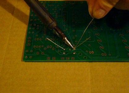
Apply solder: Touch the tip of the soldering iron to the component lead and PCB pad simultaneously. Apply solder to the joint, allowing it to melt and flow around the lead and pad. Use just enough solder to create a small, concave fillet.
-
Remove the soldering iron: Once the solder has flowed properly, remove the soldering iron from the joint and allow the solder to cool and solidify. Avoid moving the component or PCB during this time to prevent disturbing the joint.
-
Trim the leads: After the solder has cooled, use wire cutters to trim the excess component leads close to the solder joint.
-
Inspect the solder joints: Visually inspect each solder joint to ensure that it is shiny, smooth, and properly formed. A good solder joint should have a concave fillet that completely surrounds the component lead and PCB pad.
-
Clean the PCB: Once all components are soldered, clean the PCB with isopropyl alcohol and a lint-free wipe to remove any flux residue or debris.

Common PCB Soldering Techniques
In addition to the basic soldering process, there are several techniques that you may need to use when working with different types of components or PCB layouts:
Through-hole Soldering
Through-hole soldering involves inserting component leads through holes drilled in the PCB and soldering them on the opposite side. This technique is used for components with wire leads, such as resistors, capacitors, and some types of connectors.
Surface Mount Soldering
Surface mount soldering is used for components that have flat, leadless pads (Surface Mount Devices, or SMDs) instead of wire leads. These components are placed directly on the surface of the PCB and soldered in place. Surface mount soldering requires a steady hand and precise temperature control, as the components and pads are usually much smaller than through-hole components.
Drag Soldering
Drag soldering is a technique used for quickly soldering multiple surface mount components in a row. The soldering iron tip is dragged along the pads, melting the solder and creating a continuous joint between the components and the PCB.
Reflow Soldering
Reflow soldering involves applying solder paste (a mixture of powdered solder and flux) to the PCB pads, placing the surface mount components on the pads, and then heating the entire assembly in a reflow oven. The heat melts the solder paste, creating a solid connection between the components and the PCB.
Troubleshooting and Repair Techniques
Even with careful soldering, mistakes can happen, and repairs may be necessary. Here are some common troubleshooting and repair techniques:
Desoldering
Desoldering involves removing a component or solder from a PCB. To desolder a component, use a solder wick (desoldering braid) or a desoldering pump to remove the solder from the joint, then gently lift the component from the board using tweezers.
Resoldering
If a solder joint is found to be defective (e.g., dull, cracked, or incomplete), it may be necessary to resolder the joint. To resolder, first desolder the joint to remove the old solder, then clean the component lead and PCB pad before applying fresh solder.
Jumper Wires
If a PCB trace is damaged or a connection needs to be made between two points on the board, a jumper wire can be used. Jumper wires are short lengths of insulated wire that are soldered between the two points, creating an electrical connection.
PCB Soldering Best Practices and Tips
To ensure the best results when soldering your PCB, follow these best practices and tips:
-
Keep your soldering iron tip clean and tinned: Regularly wipe your soldering iron tip on a damp sponge or brass wool to remove oxidation and debris. Apply a small amount of solder to the tip to keep it tinned and promote better heat transfer.
-
Use the right amount of solder: Apply just enough solder to create a concave fillet around the component lead and PCB pad. Too little solder can result in a weak or incomplete joint, while too much solder can cause short circuits or impede heat transfer.
-
Control your soldering iron temperature: Use the lowest temperature that allows the solder to melt and flow properly. Excessive heat can damage components or cause the PCB substrate to delaminate.
-
Work quickly and efficiently: To minimize the risk of heat damage, solder each joint as quickly as possible while still ensuring a proper connection. Avoid keeping the soldering iron on a joint for too long.
-
Practice proper technique: Maintain a steady hand and good posture while soldering. Hold the soldering iron like a pencil and use your other hand to support the PCB or components as needed.
-
Keep your workspace clean and organized: A clean, well-organized workspace will help you work more efficiently and reduce the risk of errors or accidents.
Frequently Asked Questions (FAQ)
- What is the difference between lead-based and lead-free solder?
-
Lead-based solder, typically Sn60Pb40, contains 60% tin and 40% lead. Lead-free solder, such as Sn96.5Ag3.0Cu0.5, does not contain lead and is more environmentally friendly. Lead-free solder usually has a higher melting point and may require different soldering techniques.
-
How do I select the right soldering iron tip for my project?
-
Choose a soldering iron tip that matches the size and type of components you will be soldering. For most through-hole components, a conical or chisel tip is suitable. For surface mount components, a fine point or chisel tip may be more appropriate.
-
Can I solder without flux?
-
While it is possible to solder without flux, it is not recommended. Flux helps to clean the surfaces of the components and PCB pads, promoting better solder adhesion and preventing oxidation during the soldering process.
-
How can I prevent static damage to sensitive electronic components?
-
To prevent electrostatic discharge (ESD) damage, use an ESD-safe workstation, including an ESD mat, wrist strap, and grounded tools. Always handle sensitive components by their edges or packaging, and avoid touching the leads or pins directly.
-
What should I do if I accidentally bridge two solder pads?
- If you accidentally create a solder bridge between two pads, use a solder wick (desoldering braid) to remove the excess solder. Place the wick on the bridge and apply heat with your soldering iron, allowing the solder to wick up into the braid. Repeat the process until the bridge is removed.
Conclusion
PCB soldering is a critical skill for anyone working with electronic circuits. By understanding the tools, materials, and techniques involved, you can create strong, reliable solder joints that will ensure your projects function as intended. Remember to work safely, use the proper tools and materials, and practice good soldering techniques to achieve the best results.
With patience, practice, and attention to detail, you will be able to confidently tackle a wide range of PCB soldering projects, from simple repairs to complex circuit designs.
| Component Type | Soldering Technique | Tips |
|---|---|---|
| Through-hole | Standard soldering | – Use a conical or chisel tip – Apply solder to both the component lead and PCB pad – Create a concave fillet around the lead and pad |
| Surface Mount (SMD) | Surface mount soldering | – Use a fine point or chisel tip – Apply solder to the component pad and PCB pad simultaneously – Use tweezers to hold the component in place while soldering |
| Multiple SMD components in a row | Drag soldering | – Use a chisel tip – Apply solder to the first pad in the row – Drag the soldering iron along the pads, melting the solder and creating a continuous joint |
| SMD components on an entire PCB | Reflow soldering | – Apply solder paste to the PCB pads – Place the SMD components on the pads – Heat the entire assembly in a reflow oven to melt the solder paste |
By mastering these PCB soldering techniques and following best practices, you will be well-equipped to tackle a wide range of electronic projects and repairs. Happy soldering!


Leave a Reply