High density interconnect (HDI) rigid-flex PCBs provide unique benefits that make them an increasingly popular choice for electronics manufacturers. This article explores what HDI rigid-flex PCBs are, their key advantages, and some of their applications.
What Are HDI Rigid-Flex PCBs?
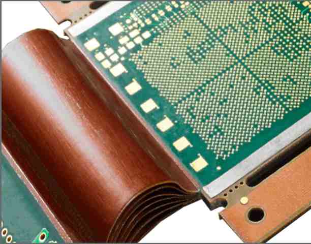
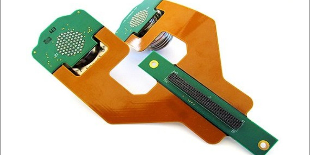
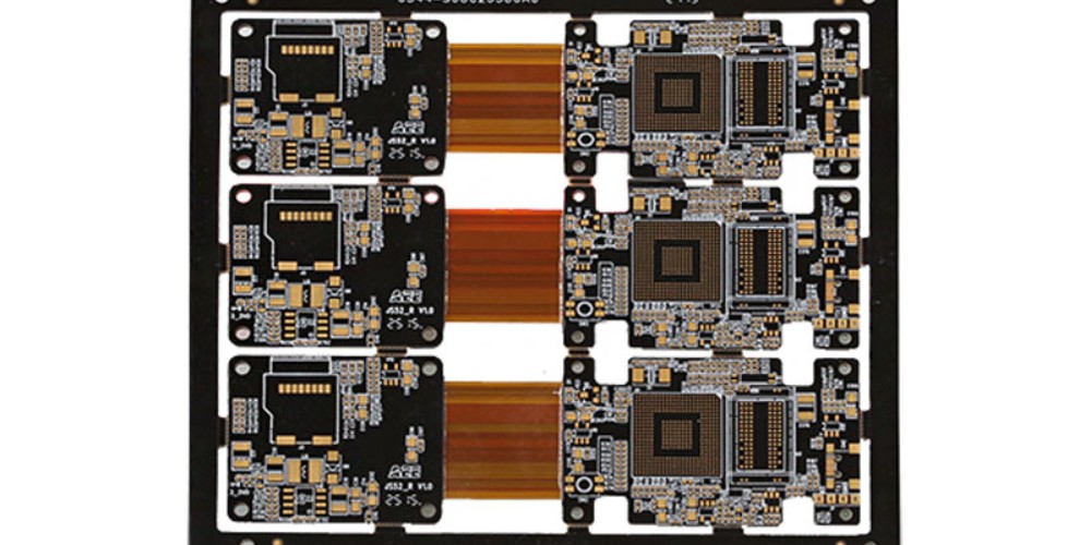
Rigid-flex PCBs integrate both rigid and flexible materials onto one board. They contain rigid board sections interconnected by flexible circuitry. HDI takes rigid-flex PCBs even further by incorporating stacked vias and microvias to achieve higher component densities.
HDI enables:
- Extremely close track and gap dimensions
- Stacked microvias
- Thinner dielectric materials
- Buried and blind vias
This makes it possible to pack more components into a smaller surface area and create more compact PCBs overall. The rigid sections provide sturdiness and structure, while the flexing regions allow dynamic movement and installations in tight spaces.
Key Benefits of Using HDI Rigid-Flex PCBs
Space and Weight Savings
HDI rigid-flex PCBs facilitate considerable space savings versus traditional rigid boards. The flexible folds and small features permit tighter component spacing and layer stacking. This condenses the electronics package for a more compact design. Eliminating connectors between separate rigid boards also saves space.
The smaller overall footprint results in considerable weight savings, which is particularly useful in aerospace, defense, and portable electronics applications. HDI technology enables lighter, more portable products.
Enhanced Reliability
With rigid-flex PCBs, the flexing regions absorb stresses and strains instead of transferring them to solder joints. The dynamic flexing also resists damage from vibrations and impacts. This improved durability over purely rigid boards reduces failures from cracked solder joints, fractures, and component detachment.
The uniform expansion and contraction provided by the flexible sections additionally minimizes stresses from thermal cycling. HDI processing further enhances reliability by eliminating drilled holes in favor of microvias created with lasers. The precise laser drilling reduces failures associated with traditional drilling.
Design Flexibility
HDI rigid-flex PCBs enable more creative, complex circuit geometries not realizable with rigid boards. The bending portions allow three-dimensional arrangements to fit products with unique shape requirements. They facilitate installations in tight spaces and simplifying routing for densely packed electronics.
HDI processing permits even higher component densities and thinner layers, expanding layout options. Rigid-flex PCBs also support embedding components and passive devices to further optimize circuit architectures. The combination of rigidity, flexibility, and density provides unprecedented design flexibility.
Improved Electrical Performance
The shorter traces and smaller features of HDI rigid-flex PCBs allow faster signal speeds, lower noise, less crosstalk, and better signal integrity. Replacing connectors between rigid boards with flexing interconnects also increases performance by lowering inductance and capacitance. The shorter connections enable higher frequencies and data rates.
Cost Reduction Potential
Despite their advanced technology, rigid-flex PCBs can potentially lower costs compared to rigid boards plus cables in certain applications. Eliminating edge connectors and separate flex circuits simplifies the assembly process and reduces labor requirements.
The miniaturization can also decrease materials costs by allowing smaller and fewer boards. The enhanced reliability saves costs by reducing failures in service. While rigid-flex PCBs have a higher upfront cost, they can save considerable costs long-term in the right application.
HDI Rigid-Flex PCB Applications
Aerospace and Defense
Size and weight reduction are imperative in aerospace systems, making rigid-flex PCBs highly advantageous. They also withstand intense vibrations and wide temperature swings common in aircraft and spacecraft. HDI technology provides the enhanced reliability needed for critical defense and guidance systems.
Portable Consumer Electronics
HDI rigid-flex PCBs allow maximizing functionality while minimizing size and weight in smartphones, tablets, and laptops. The compact, lightweight boards are ideal for the continual trend toward lighter, thinner, and more powerful mobile devices.
Medical
Medical devices often require dense electronics to be packed in ergonomic packages. HDI rigid-flex PCBs provide the ideal blend of density, reliability, and flexibility to meet size constraints while operating reliably in vital medical equipment.
Automotive
The small size, durability, and reliability also suit HDI rigid-flex PCBs well for automotive applications. They withstand vibrations while providing weight savings and innovative packaging geometries in constrained, harsh under-hood environments.
Internet of Things (IoT)
Many IoT edge devices are compact and benefit from space savings. HDI rigid-flex PCBs allow packing more functionality into very small programmable logic controllers, sensors, and connectivity modules powering the growth of IoT.
Frequently Asked Questions About HDI Rigid-Flex PCBs
Here are answers to some common questions about HDI rigid-flex PCBs:
What are the key differences between rigid, flex, and rigid-flex PCBs?
- Rigid PCBs use stiff, fibreglass-reinforced boards without any flexing regions. They provide structural support but no dynamic movement capabilities.
- Flex PCBs contain only thin, flexible circuit materials without any rigid sections. This allows dynamic contours and motion but not firm mechanical support.
- Rigid-flex PCBs integrate both rigid board sections and flexing materials into one circuit board. This combines support and structure with flexibility in select areas.
How do designers determine where to place rigid versus flex regions on a rigid-flex PCB?
Designers position rigid sections where components will mount or where stiffness is needed. Flexible portions are located where the circuit board needs to bend and contour. Analysis factors like required bending radius and layer stackup influence positioning. Planning ahead for harsh conditions is also important.
Can passive components be embedded in an HDI rigid-flex PCB?
Yes, embedding passive components like resistors, capacitors, and inductors within the PCB layers is a key benefit of rigid-flex boards. Embedded passives simplify the overall design while taking advantage of HDI’s enhanced component densities.
How are components assembled onto HDI rigid-flex PCBs?
Soldering is typically used to attach components to the rigid portions of HDI rigid-flex PCBs, similar to conventional PCB assembly. Flexible sections often use conductive epoxy instead of solder, which withstands dynamic bending better than solder joints.
How should HDI rigid-flex PCBs be handled and protected during assembly and operation?
Avoid excessive flexing and prevent sharp bends below the minimum bend radius. Use board supports to limit flexing if needed. Prevent pulling, twisting, and impact damage to the flexible elements during handling. Avoid particle contamination and use conformal coatings to protect the circuits.
Conclusion
HDI rigid-flex PCBs offer unmatched benefits in electronics packaging applications requiring dense, reliable, and adaptable circuit boards. HDI enables lightweight, compact, high-performance designs not feasible with traditional rigid PCBs. As HDI and rigid-flex technology continue advancing, they will transform electronics into ever smaller and more capable packages across countless industries.


Leave a Reply