Introduction to Aerospace PCBs
Printed circuit boards (PCBs) are an essential component of almost every aerospace system. From commercial jetliners to deep space probes, PCBs provide the foundation for avionics, flight control systems, communication systems, and more.
However, aerospace PCBs have very different design and manufacturing requirements compared to commercial or consumer electronics. The challenging aerospace environment, criticality of systems, and high reliability requirements impose stringent standards on aerospace PCB design, materials, assembly processes, and quality control.
In this article, we’ll provide an overview of key considerations for aerospace PCB assembly to achieve the high reliability and quality needed for mission-critical applications.
Materials Selection
Aerospace PCBs must be fabricated from materials engineered to withstand the extreme conditions of the aerospace environment, including:
- Temperature extremes from -55°C to over 125°C
- Vibration, shock, and acceleration forces
- Pressure and humidity changes
- Exposure to radiation
Common Materials for Aerospace PCBs
| Material | Description |
|---|---|
| FR-4 | Flame retardant glass-epoxy laminate. Most common PCB material but limited temperature range. |
| Polyimide | High temperature resistance above 200°C. Used for flex PCBs. |
| PTFE | Polytetrafluoroethylene offers excellent electrical and temperature insulation. |
| Ceramic and Quartz | High frequency and temperature performance but brittle. |
| Rogers Laminates | Woven glass reinforced thermoset laminates with improved dielectric properties. |
PTFE, polyimide, and Rogers laminates like RO4000® series are popular choices for aerospace PCBs. The materials provide a balance of electrical and mechanical properties to withstand aerospace environments.
PCB Design Rules
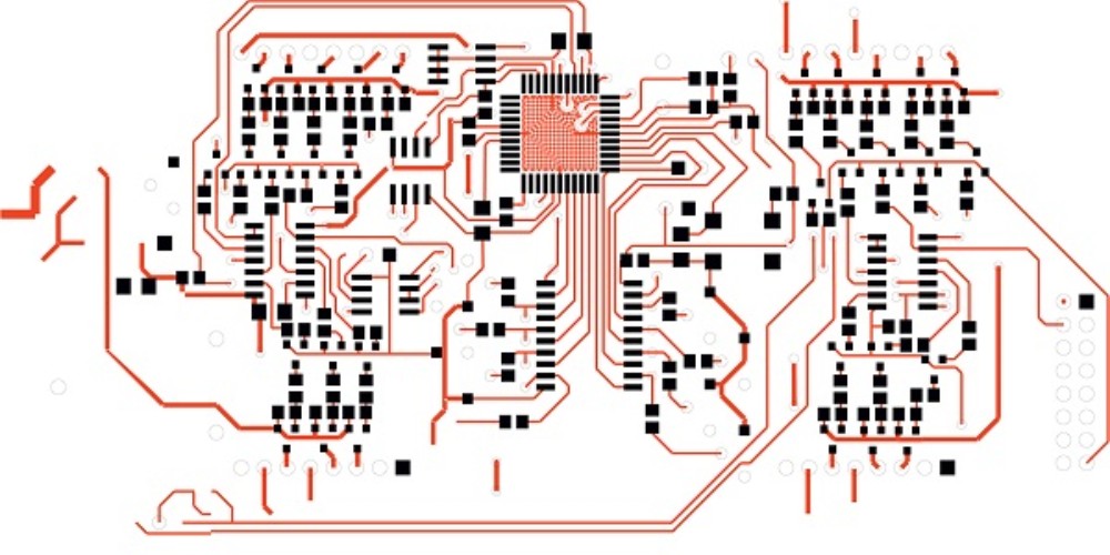
Aerospace PCBs must adhere to design requirements focused on reliability rather than just cost and manufacturability.
Key differences in design rules include:
- More conservative trace widths and spacing
- Larger annular rings around plated through holes
- Limitations on the use of blind and buried vias
- Minimal or no microvias
- Very large solder pads and generous solder masking
- Robust ground planes with plenty of vias
Following “overdesigned” rules ensures aerospace PCBs are resistant to issues like stress cracking, electrical shorts, and opens during temperature changes and vibration.
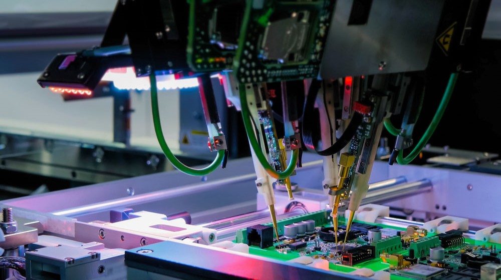
Soldering Processes
The soldering process must produce highly reliable solder joints that will not fail under temperature cycling or vibration. The presence of even one cold solder joint could compromise an entire mission-critical system.
Common soldering methods include:
- Selective wave soldering – Targeted wave solder machine for attaching through-hole components. Provides excellent hole fill.
- Hand soldering – For sensitive components. Allows inspection and rework of each joint.
- Convection reflow – Solder paste and convection oven used primarily for SMT components. Close control of temperature profile is critical to avoid damaging boards.
- Vapor phase reflow – Uses an inert vapor instead of air to evenly heat entire boards for reflow. Reduces thermal shock.
Flux residues must be thoroughly cleaned after soldering to prevent corrosion or electrical leakage during operation. Cleanliness validation testing such as IPC J-STD-001 is advisable.
Conformal Coating
Applying a thin polymeric conformal coating to aerospace circuit boards improves resistance to moisture, chemicals, and short circuits between tightly spaced conductors.
Common aerospace conformal coatings:
- Acrylic – Flexible coating resistant to moisture and solvents. Easy to apply and repair.
- Urethane – Tough abrasion resistant coating.
- Silicone – Withstands high temperatures up to 200°C. Prepared boards must have low moisture.
- Paraxylene – Thin conformal coating with excellent chemical resistance.
Conformal coatings must be selectively applied to avoid interfering with test points, connectors, heat sinks or moving components. Regular inspection ensures full coverage without gaps or air bubbles.
Counterfeit Components
The use of counterfeit electronic components is a major reliability risk for aerospace systems. Fake or recycled devices can fail prematurely or unpredictably.
Strict procurement controls must be implemented including:
- Purchasing only from authorized suppliers and channels
- Mandating full traceability documentation back to the component manufacturer
- Testing and inspection regimens to catch counterfeits
- Destroying rejected parts to prevent re-entry
Quality Control and Inspection
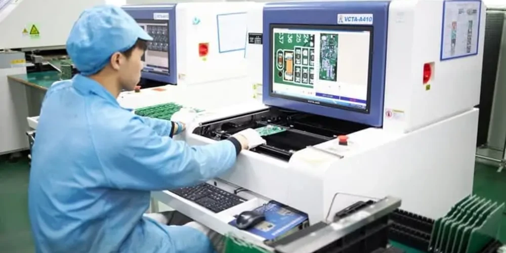
Extensive testing and quality control steps are necessary to validate the quality and reliability of aerospace PCB assemblies, including:
| Inspection Method | Purpose |
|---|---|
| Visual Inspection | Verify conformance to drawing requirements, identify defects |
| Dimensional Inspection | Check PCB size, hole positions, pad sizes, etc. match specifications |
| Netlist Testing | Validate circuit netlist matches schematic |
| In-circuit Testing | Dynamic electrical testing to simulate inputs and check outputs |
| X-Ray Inspection | Detect potential shorts, opens, and air gaps under components or in vias |
| Vibration Testing | Validate solder joint and component integrity under vibration |
| Environmental Stress Screening | Temperature, vibration, voltage stress testing to precipitate latent defects |
| Cleanliness Testing | Ion chromatography, flourescence, or cleanness testing per IPC standards |
Thorough testing and inspection processes combined with quality system controls provides the highest level of confidence in aerospace PCB assembly quality and reliability.
FAQ
What standards are used for aerospace PCB design and manufacture?
Key standards include:
- IPC J-STD-001 – Requirements for Soldered Electrical and Electronic Assemblies
- IPC-A-610 – Acceptability of Electronic Assemblies
- IPC-6012 – Qualification and Performance Specification for Rigid Printed Boards
- IPC-6018 – Qualification and Performance Specification for High Frequency (Microwave) Printed Boards
How are aerospace PCBs different than commercial PCBs?
Aerospace PCBs are overdesigned for reliability versus cost, use exotic materials to withstand extreme conditions, follow tightly controlled assembly processes, undergo extensive testing, and meet stringent quality standards.
What is the most common cause of failure for aerospace PCBs?
Solder joint failures due to thermal cycling, vibration, and shock. Robust design rules, quality soldering, inspection, and conformal coating help minimize these risks.
How can PCB assemblies be tested for space or satellite use?
Vibration, thermal cycling, thermal shock, and sometimes radiation can be simulated to qualify assemblies for the space environment. Burn-in screening and monitoring of key electrical parameters is also common.
What is the average operating temperature range for aerospace PCBs?
Military avionics operate from -55°C to 125°C. Space craft can see wider temperature swings from -190°C to over 180°C, depending on the environment and mission profile. Materials, design, and testing must account for worst-case temperatures.
Why are aerospace PCBs so much more expensive than commercial PCBs?
The exotic materials, low volumes, challenging specifications, overdesigned layouts, and extensive inspection and testing required for aerospace PCBs leads to higher costs. However, the high reliability is critical for avoiding catastrophic failures in mission-critical aerospace systems.


Leave a Reply